China wholesale Contact&Relay&Starter - Wholesale hw-RST 25 Phase Failure Under Overvoltage Relay Sequence Relay – Hawai
China wholesale Contact&Relay&Starter - Wholesale hw-RST 25 Phase Failure Under Overvoltage Relay Sequence Relay – Hawai Detail:
Connection
The RST 25 can be connected as following in the installation diagram:
FlG1: Connection of the relay before operation.
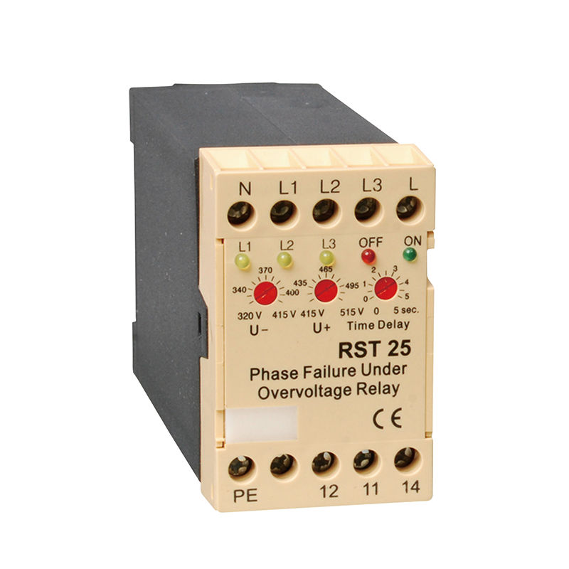
When the relay is connected as in FIG 1, the three yellow LED’s L1,L2 and L3 light up when the power supply A1 phase L, the A2 Neutral, and the three phases”L1,”L2″and”L3″are properly connected.
If there is no under of overvoltage, phase failure of phase sequence, the green LED lights up,(terminals 11 and 14 are closed ) and the relay is ready for operation.
FIG2: Connection of the relay after operation.
When the relay is connected as in FIG 2,(the power supply Al phase L, the A2 Neutral are properly connected) after operation, the three phases”L1″,”L2″and”L3″are connected, andthere is no under of overvoltage, phase falure, phase sequence, the green LED lights up(terminals 11 and
14are closed) and the relay is ready for self retaining.
It is also possible to connect the power supply after operation in FIG2.
By both FIG’s 1 and 2, the terminal “PE”must be grounded.
Undervoltage
The desired undervoltage limit can be adjusted down to -25% UN.
Overvoltage
The desired overvoltage limit can be adjusted up to +25% UN.
Asymmetry
When adjusting over-and undervoltage limit, the asymmetric limit is also adjusted.
Time Delay
The switch off time can be adjusted by the potentiometer “Time’ Delay”from 0.1….5 seconds. With this function it is possible to adjust the time for the identification of the failure.
Contactor Control
If a phase fails during operation at load or one of the contacts of the contactor or circuit breaker is defect,(contact bounce or scorched contacts), RST 25 recognizes the failure, and also the feedback voltage, and switches off depending on the setting of “Time Delay”
The RST 25 controls the phase shift. If there is a phase failure during operation the angle from the feedback voltage is 30° and the RST 25 recognizes this failure.
Product detail pictures:

Related Product Guide:
We generally believe that one's character decides products' top quality, the details decides products' high-quality ,along with the REALISTIC,EFFICIENT AND INNOVATIVE team spirit for China wholesale Contact&Relay&Starter - Wholesale hw-RST 25 Phase Failure Under Overvoltage Relay Sequence Relay – Hawai , The product will supply to all over the world, such as: Afghanistan, Haiti, Lisbon, You can always find the solutions you have to have in our company! Welcome to inquire us about our product and anything we know and we can help in auto spare parts. We have been looking forward to work with you for a win-win situation.
The company has rich resources, advanced machinery, experienced workers and excellent services, hope you keep improving and perfecting your products and service, wish you better!


